Linear actuators RH 1250
strokes 80 to 250 mm
manual-hydraulic version

Principal use
• Height adjustment of hospital and nursing beds as well as mobile nursing chairs
• Height adjustment of patient transporters and therapy couches
• Adjustment of examination and care chairs as well as childbirth beds
• Height adjustment of instrument tables
• Actuator for lifting modules and lifting tables
Description
Linear actuators RH 1250 are manually operated, hermetically sealed, hydro-mechanical actuators for linear adjusting procedures.
The compact design contains the pump piston and the valve technology. Also the oil reservoir and the plunger cylinder are integrated. The hydraulic transmission in connection with the manual operation allows a good dosage of very high forces. Important for that are also the mechanics with minimum clearance as well as the sensitive responding valves with exactly defined switching points.
In principle only push forces can be generated.

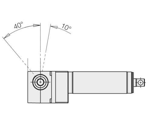
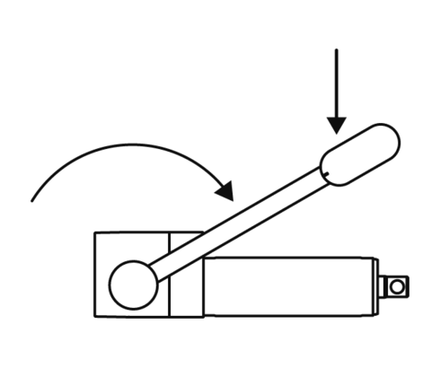
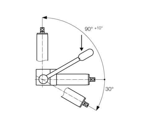
The plunger rod is extended by reversible rotation of approx. 40° by an operating lever at the operating shaft. The recommended lever length is approx. 300 mm.
To retract the plunger cylinder, the operating shaft has to be turned to the opposite direction by approx. 10°. The operating shaft returns automatically.
Functioning
All versions of the RH 1250 are operated with an operating lever, that is pinned at the operating shaft. The integrated flow control valve provides for an uniform descent speed in all load conditions.
Due to the possibility to get a drilled operating shaft, the actuator can quickly be installed and put into operation.
It has to be considered that the user's construction always acts with push force onto the actuator.
The actuator has a high safety against overload. In the case of overload it is not possible to continue pumping the actuator, but descent is possible. The operator has to make sure that the actuator is not overloaded.
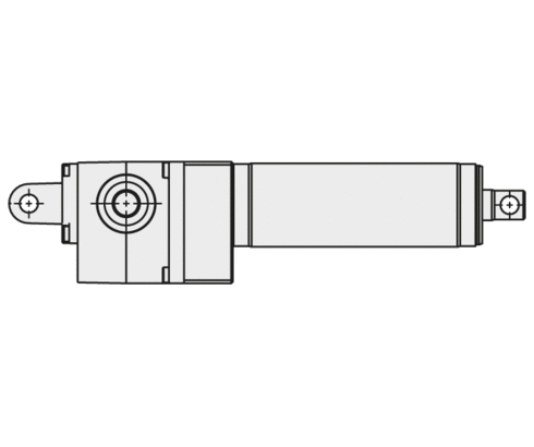
The linear actuators RH 1250 have 1 location hole Ø 12.1 mm in the plunger and 2 centring pivots Ø 38 mm for the connection of user's constructions.
Besides the standard mounting with centring pivot Ø 38 mm mounted at the housing, the RH 1250 can be delivered with fork mounting or flange mounting.
The user's construction must exclude side loads and forced conditions. The centring pivots Ø 38 mm are unlacquered.
There are two different operating directions of the pump lever.
Dependent on the operating direction, the admissible mounting positions have to be considered.
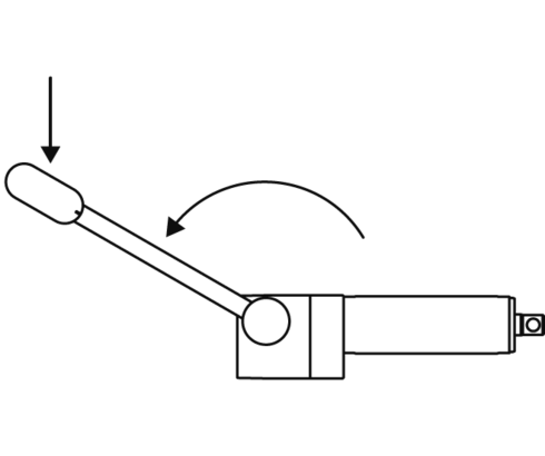
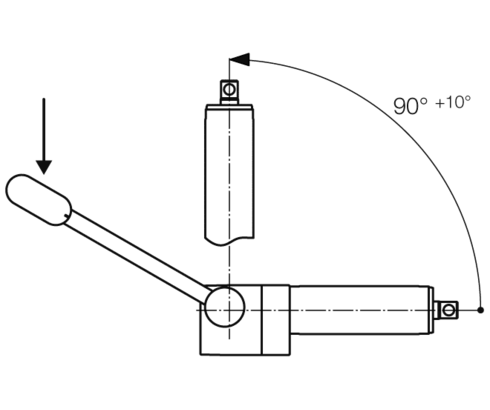
Operating direction A
Pump lever counterclockwise (figure 5a)
Admissible mounting positions as per figure 5b.
Operating direction D
Pump lever clockwise (figure 6a)
Admissible mounting positions as per figure 6b.
Material
body: aluminium
operating shaft: steel, corrosion resistant
plunger: steel, corrosion resistant
Colours
• unlacquered
• 2 = RAL 9016 traffic white
• 3 = RAL 9006 white aluminium
• 4 = RAL 9005 black
• 5 = RAL 7035 light grey
• 6 = RAL 7038 agate grey
Available on request:
• stroke lengths up to 600 mm in gradations of 50 mm (up to lifting force 6,500 N)
• descent actuation by pushing
• descent actuation by turning
• front-side thread M8 in the plunger
• versions with low residual magnetism for MRT applications
• other descent speeds
• other colours
• customised special actuators
| Item no. | CAD data | type | stroke [mm] | fixation | max. force to push [N] | |
|---|---|---|---|---|---|---|
|
Item no.
|
CAD data
|
Properties
| ||||
|
Item no.
|
CAD data
|
Properties
| ||||
|
Item no.
|
CAD data
|
Properties
| ||||
|
Item no.
|
CAD data
|
Properties
| ||||
|
Item no.
|
CAD data
|
Properties
| ||||
|
Item no.
|
CAD data
|
Properties
| ||||
|
Item no.
|
CAD data
|
Properties
| ||||
|
Item no.
|
CAD data
|
Properties
| ||||
|
Item no.
|
CAD data
|
Properties
| ||||
|
Item no.
|
CAD data
|
Properties
|
| Item no. | CAD data | Description |
|---|---|---|
|
Item no.
|
CAD data
|
Description
Foot pedal, pre-drilled
for the arrangement of 90° to the shaft bore hole
as per data sheet L7.101
|
|
Item no.
|
CAD data
|
Description
Foot pedal, without bore hole
for application-specific arrangement
as per data sheet L7.101
|
|
Item no.
|
CAD data
|
Description
Hand lever, pre-drilled
for the arrangement of 90° to the shaft bore hole
as per data sheet L7.101
|
|
Item no.
|
CAD data
|
Description
Hand lever, without bore hole
or application-specific arrangement
as per data sheet L7.101
|
|
Item no.
|
CAD data
|
Description
Bearing block for bearing eye Ø38 mm
as per data sheet L7.101
|
|
Item no.
|
CAD data
|
Description
Pedal cover, black
as per data sheet L7.101
|
Foot pedal
• pre-drilled for the arrangement of 90° to the shaft bore hole
• without bore hole for application-specific arrangement
Hand lever
• pre-drilled for the arrangement of 90° to the shaft bore hole
• without bore hole for application-specific arrangement.
Bearing block
For location of the RH 1250 at the bearing eyes Ø 38
two of each required
Pedal cover
for levers provided by the user or as spare part
Take advantage of the free benefits of our login area:
- CAD data download
- Download operating instructions
Welcome back! Log in to your already existing user account.